|
Introduction
If you were to look on the internet for tutorials on Baybus construction
and information on wiring, you can find it all over. The problem is,
it's written BY people who understand it FOR people who understand it.
Does that make sense? Not to me. How can I make a claim like that? Easy,
a month ago, I didn't understand it, any of it. I read every article
I could find on the subject, and had to piece together 200 steps from
50 articles, It was quite grueling, but I did manage to figure it out.
Here it is, in it's simplest form. No complex details. No unneeded information.
Direct, and to the point.
Buying the Pieces
You have 3 choices. You could buy a cheep version yourself at $25.00
- $35.00 (since you are cutting your case front panel, you can't go
back and just buy a new one later). You could buy it from an online
discount store for like $50.00 - $60.00 for everything with shipping.
The third was is the easiest, safest and cheapest. Make your life easy
and just buy the kit from https://subdiv.net
for $49.95. The kit includes everything you need, as well as a 25 minute
installation tutorial. The video includes even more detail than is included
here.
What You Need
The Kit Comes With
- Project Box, 4 DPDT Switches, 4 Blue LEDs, 4 Red LEDs, 8 LED Clips,
1 470ohm Resistor Network, 8 LED Cables, 1/8-in Heatshrink, 22g Red
Wire, 22g Black Wire, 2 Male Molex Connector, 2 Male Molex Pins, 2 Female
Molex Connector, 2 Female Molex Pins and How-to Guide.
Other
Stuff - Drill with 1/4in bit, Soldering Iron, Hair Dryer, Scissors,
and Pliers
| Step
One - Overview |
| Here
is a diagram of all the parts and all the wires. Each line is a
different color, but when wiring it doesn't matter what color wire
you use. Just keep in mind to use Black for your ground wires when
instructed (not 100% needed, but makes life easier with a standard).
Other than that, use black, red, blue green, whatever, it doesn't
matter. Each line in the diagram represents a wire that connects
2 pieces. The image below links to a much larger picture that you
can print out for reference. |
|
|
| Step
Two- The Faceplate |
|
|
|
Take
your switches and space them out on the faceplate, and mark the
area off. If you make a diagram on the computer then print it
out, you know it will be centered. Cut out the holes for the 4
switches and 8 LED lights. Place the lights and switches onto
the plate. Make sure everything fits and is centered.
|
|
|
|
While actually doing the wiring, I recommend that you leave the
switches on the faceplate and mount it onto a vise. This way you
can work with both hands free, and with easy access to the switches.
Later on, you can place it into the box itself. During the tutorial,
I built it inside the box. My bad, don't do that.
|
| |
| Step
Two- The Project Box |
|
Once
you have the faceplate, cut the needed holes in the box. I was
dissatisfied with the project box that comes with the kit, so
I would recommend a box that is 4"x2"x1", otherwise
you will most likely have fitting problems. If you are going to
use the supplied box, you should reevaluate how you want these
cuts to be on the box, since it's a different size, this article
won't be 100% accurate for the box cuts.
|
 Make 4 holes
for the switches, but make 8 gouges in the box for the LED lights...
it's a tight fit.
Make 4 holes
for the switches, but make 8 gouges in the box for the LED lights...
it's a tight fit.

 Also cut 4
holes on the top and bottom of the case for the LED wires that
will be coming out the top and bottom.
Also cut 4
holes on the top and bottom of the case for the LED wires that
will be coming out the top and bottom.
 The last holes
will be on the back for the speaker terminal and the binding post.
The last holes
will be on the back for the speaker terminal and the binding post.

 |
| Step
Three- The Wiring |
|
As
I said, work on the wiring outside of the box, and put it inside
later. For now, follow the diagram as for which wires jump the
others.
|
 Start with
the middle. Solder a 6" red wire, one end is loose, the other
connects to the left middle of the switch. Next, solder another
wire onto the same joint on the next switch, and connect that
one with the one next to it. Do the same with the black wire as
well. Basically, the 6" will later be connected to the molex
for power. You then leapfrog each joint to connect all the wires
down the middle.
Start with
the middle. Solder a 6" red wire, one end is loose, the other
connects to the left middle of the switch. Next, solder another
wire onto the same joint on the next switch, and connect that
one with the one next to it. Do the same with the black wire as
well. Basically, the 6" will later be connected to the molex
for power. You then leapfrog each joint to connect all the wires
down the middle.
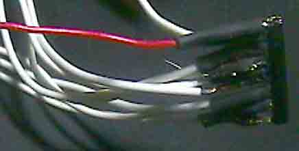
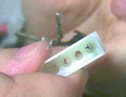
 Take the LED
connector and cut off the rounded end, we will be using the part
that usually plugs onto the motherboard.
Take the LED
connector and cut off the rounded end, we will be using the part
that usually plugs onto the motherboard.
 
 Once you have
cut and stripped all 16 wires, solder the black wire to the top
right and lower left terminals. Next, run a wire from the top
left terminal to the lower right terminal. Screw the speaker terminal
and the binding post into the project box if you haven't already.
When you finish that, you will have one joint left on the switch.
Connect that one to the speaker terminal. At this point you have
alot of wires and a big mess.
Once you have
cut and stripped all 16 wires, solder the black wire to the top
right and lower left terminals. Next, run a wire from the top
left terminal to the lower right terminal. Screw the speaker terminal
and the binding post into the project box if you haven't already.
When you finish that, you will have one joint left on the switch.
Connect that one to the speaker terminal. At this point you have
alot of wires and a big mess.
 Solder a red
wire to the network resistor about 2-3" long on one of the
ends. Then solder each of the white wires from the LED connector
onto each of the remaining pins.
Solder a red
wire to the network resistor about 2-3" long on one of the
ends. Then solder each of the white wires from the LED connector
onto each of the remaining pins.
1. Be careful, they break easily.
2. If you don't use heatshrink anywhere else, at least use it
here. It's a tight fit, and you don't want any of the wires touching.
3. You will have one extra pin when your done, so if you break
one by accident, you have another shot. |

 |
 |
Connect
the red wire from the resistor to a Solder Shield. This doesn't
come with the kit for some reason, but you need one because you
cannot solder to the binding post, which is where we will be placing
the shield. You will run a second wire out to nowhere about 6"
long, also connected to the shield.

|
Now
things are going to start getting tight and hard to handle. Take
the LED connectors and stick each one through the holes in the
top and bottom of the project box. NOTE: The connections are backwards.
So take the connectors on the bottom of the switch and run it
through the top holes. Take the connectors on the top and run
that through the bottom of the box.
 
The last part of this step is to carefully jam all the wires into
that little box. Take the switches off the front panel, if that
was how you assembled all this wiring, and stick the snitches
through the holes in the box AND the faceplate so that you are
connecting the box with the faceplate. Once you have jammed everything
in the box (LED connectors hanging out), and the box joined with
the faceplate, connect the LED lights. Take the extra wire and
carefully slide that back into the box as well. NOTE: The white
wire is the positive, and so is the longest LED pin. The black
wire lines up with the shortest pin. The LED pins are long, so
you may cut them down with scissors if you want.

Take the molex pins and connect them to the 6" black and
2 6" red wires you have left over. Then, take the pins and
plug them into the molex connector. NOTE: if you do have 2 red
wires, label one of them as 5v the other is 12v. The 12v one comes
from the binding post, and that will line up with the yellow wire
from the power supply. The 5v one comes from the middle terminals
on the switches, and that will line up with the red wire from
the power supply. Place the black wire in either of the 2 open
middle holes in the molex.


|
| Step
Four - Connecting the Fans |
| |
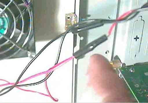
Most fans have 2 or 3 wires, a red one, a yellow one and a
black one. The Black is always the ground. The black wire will
plug into one of the speaker terminals. The red, yellow, blue
(whatever) wires will all connect to the binding post.

If your fan has red and yellow wires, connect them together, that's
fine.

If you have more than one fan you would like to have working off
one switch, connect them together in the speaker terminal.

If In this last picture, you can see the red wires are plugged
into the post. I had pre-spliced all the other wires earlier in
the connection, so that I only had 3 wires actually plugged in
there, otherwise it would be a tight fit at the post. Lastly,
I plugged each black wire into each speaker terminal. Ignore the
red/black switches, we aren't using them for that, just one for
each fan. |
| Step
Five- Conclusion |
| This
project sucks. Look, I could lie to you and say it's easy, but it's
not. But I do think that with this tutorial, and the one at CaseEtc,
you can figure it out. Of course, you could just go to the store and buy your own for half the cost... |
|


